Sunday, April 10, 2011

CNC USB Motion Controller

Our Version of the CUMC

This version of the Planet-CNC, CNC USB Motion Controller is very similar to the original with the following differences: added a 5V regulator, added a connector for a USB panel mount, changed the ICSP to the PicKit2 pinout and changed sip resistors to 10 pin (readily available). The 10 pin driver connector is PMinMO compatible and is correctly oriented. The USB connector has been moved to the front for insertion thru the front panel of the electronic enclosure.

In addition to the CUMC, a jog switch panel pcb and a limit switch junction pcb are in the works. At some point a enclosure layout will be added to this post.
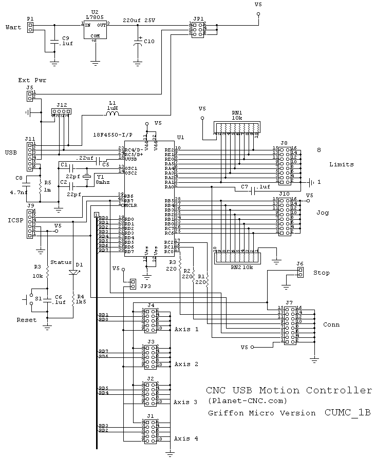


Bill of Materials for CNCCUMC_1B

 http://www.batchpcb.com/index.php/Products/57241


Bill of Material for C:\PCB PIC\CNC_CUMC_01B.PCB

On 4/9/11 at 5:59:46 PM


Count
Label-Value
Pattern
Designation(s)
Mouser #


2
22pf
cap100s
C1 C2
80-C315C220J1G
1
220uf
C+300D140
C10
647-UHE1E221MPD
3
.1uf
cap100s
C3 C5 C6
80-C320C104M5R
3
.1uf
cap100
C7 C9
80-C320C104M5R
1
.22uf 50V 20%
cap100
C4
80-C320C224K5R
1
.0047uf
cap100
C8
80-C315C472K5R
1
1N5817
DIODE0.35
D1
511-1N5817
1
ferrite bead
AXIAL0.3
FB
623-2743001112LF
4
IDC10-S
XIDC10
J1 J2 J3 J4
517-D2510-6002-AR
3
IDC16-S
XIDC16
J10 J7 J8
517-D2516-6002-AR
1
USB-S B
USB-BS
J11
523-UE27-BC54-130
1
IDC Header 4
620454-4
J12
571-6404564
2
IDC Header 2
620454-2
J5 J6
571-6404562
1
IDC Header 6
620454-6
J9
571-6404566
1
DHeader 6
IDC6
JP1
517-836-01-04
2
SHeader 2
SIP2
JP2 JP3
517-647-01-02
1
LED green
LED
LD1
638-HLMP-1790
1
Power Jack
PJ-102A2
PB1
CUI PJ-102A Digikey
3
220R 1/8W
AXIAL0.25
R1 R2 R3
299-220-RC
1
10k 1/8W
AXIAL0.25
R4
299-10K-RC
1
1meg 1/8W
AXIAL0.25
R5
299-1M-RC
1
1K5 1/8W
AXIAL0.25
R6
299-1.5K-RC
2
10K SIP 9P
SIP9
RN1 RN2
652-4610X-1LF-10K
1
TS 3.5x6mm
SW635
S1
101-TS4311T2601-EV
1
18F4550
DIP40.6X2025
U1
18F4550-I/P
1
L7805
TO252AB
U2

511-L7805CD2T-TR
1
8mhz
XTAL4
Y1
520-HCU800-20X
1
40 pin IC socket

U1S
517-4840-6004-CP


Getting the CUMC Board Working

1) Install the USB driver and the CUMC software on your PC (See manual)

2) Using PIC programmer install Bootloader in 18F4550. I used MeLab serial programmer. PicKit2 or PicKit3 can also be used or one of your choice.

3) Connect Jumper from Jog8 to Vcc. Press reset. Led should start blinking.

4) Remove jumper and insert USB connector.

5) Start PC software.

6) Using software do: Machine-Firmware-Update

7) Firmware should update and give a response.

Assembled Board

Below is a picture of the assembled board.


Unhappily, Batchpcb failed to place the top silk screen. Why, I don't know, since it was in the zip file. The back of the pcb has a ground plane and the orange markers in the above layout are the ground points. This print does show the top screen for reference.

I plan to make some changes to the board once I have this prototype working. As I assembled this prototype, some changes have already been made to the layout to accommodate , for example, a jog switch pcb, etc.

The next step is to  program the 18F4550 and test the pcb.

Important Note:
Our version does not have the same 16 pin connector orientation as planet_cnc. This can be fixed during assembly by rotating the the JOG and the Limit connectors by 180 degrees. To make sure, go to planet_cnc store and double click their pcb image. Make sure the connectors have the same orientation. By doing this the connector pinout will match the manual. It should be pointed out that the planet_cnc overlay pdf is wrong and does not match the manual.

Our version 2 will fix the connector orientation problem, but will not be sent to Batchpcb until the present version is completely tested.

Update:
Since a complete electronic package is our goal, a JOG switch pcb and a limit switch pcb have been designed. The JOG pcb will mount on the electronic case front panel and the limit switch pcb will mount at the CNC router.Cabling the limit switch pcb will be as follows: IDC-16 pin on CUMC to DB-15 pin on rear panel to DB-15 pin at router to 16pin IDC. A small aluminum box on rear of CNC router will house electrical interconnects, including connectors to motors.  

Thursday, March 17, 2011

LOG: Notes and Comments

03/17/11

1) Today I received the parts to finish the fences on my router and drill press tables. Also, I have been in the market for a router designed for a router table, i.e., hight adjustment above the plate, and today Sears online had a sale on routers.  I purchased a 917542 for $60. Good price.

2) I have been exploring USB GCode interpreters. There are two open source versions available for the Arduino and a proprietary one by www.planet-cnc.com using the PIC 18F4550. One of the Arduino versions can be found at the REPRAP site and the other here,   http://dank.bengler.no/-/page/show/5471_gettinggrbl.

  Grbl:  3-axis interpreter
         Pros: It's free. To use it download code into Arduino with the IDE and then connect to it with a terminal emulator. Use the terminal to send GCode files to the Arduino. Three Arduino bits are assigned to limit switches.

        Con: There are no jogging switches. As yet there is not a PC GUI to operate Grbl.

 Planet-cnc:  4 axis interpreter
        Pros: Cost is $200. Includes assembled PCB and GUI. There are jogging and limit switches, as well as, other neat features. The firmware for the 18F4550 is not open source, but it appears to be free to use. You are even free to layout your own pcb. The license for the PC software is 69euro. You can run your CNC from a laptop, not a parallel port.

       Cons: ? Time will tell.

3) Though the CNC router base build is not finished, I will start Part 4, The Gantry Base, which will show how the adjustable linear bearings are made.

3/18/11

I added the BOM and a drawing to the Part3: Router Base. Sorry about the hand drawing, but it was quicker.

3/24/11

I have spent some time looking at the CNC USB Motion Controller of Planet-cnc to the extent that I decided to layout my own version of the PCB. The Planet-cnc site provides a DIY section with complete info for building your own hardware. There interest is in selling the PC software, ($100.). There are a number of people who have built the hardware with success. The unlicensed software will run 25 GCode statements which should be enough the get it tested.

The pcb, I have laid out, is slightly larger than theirs, I added a few features, but I did keep connector compatibility. Though I still have small changes to make to the pcb, I sent a trial run to Batchpcb. It passed with a single price of $27. for which you usually get two boards. The 18F4550 is $5.36 from Mouser and you will need a programmer such as PicKit2. I have the parts to build a prototype and should receive the pcb's in about 3 weeks. Batchpcb is cheap but slow.

I started out by thinking how I would mount the electronics in a case and connect all the parts to the front and back panels. I will make some rough drawings and put them online here. Briefly, the front panel will have 8 jogging push buttons and a USB connector. The rear panel will have connectors for the motors, limit switches, emergency stop, master fuse, USB connector and power cord. It might be interesting to put LED's for the limit switches. Inside there will be two power supplies, one for the motors and the other a 5V for the controller. The motor drivers, I have designed, have opto isolation on the input and onboard 5V regulators for driver electronics. This should protect the controller and the PC.

http://www.planet-cnc.com/

3/25/11

The pcb has been submitted to Batchpcb and, hopefully, should be here in three weeks. In the mean time I will program a 18F4550 with the bootloader and test it.

I am in the process of assembling the cnc router base, as well as, making the gantry base.

4/2/11

When I started work on the CNC Router, I first designed two modular bipolar step motor drivers: one using the L297/298 (Stepit 1) and TB6560 (Stepit 2). Rather than a single pcb with multiple drivers, the design is modular, that is, a single driver per pcb. These drivers are connected to the parallel port breakout board using PMinMO, s defacto 10 pin IDC connector standard. This turned out to be a good choice, since the CNC USB Motion Controller from Planet-CNC uses the same standard. I have now added two more drivers two my stable of drivers, in this case, unipolar drivers: the first, using the SLA7062/67M (Stepit 3) and the other using the SLA7078MPR (Stepit 4).

 Stepit 3 uses a SLA7062 or SLA7067 unipolar drivers by Sanken which is not the easiest chip to find, but find some I did. After examining the Sanken data sheets, I have designed two versions of the driver: one, with opto isolation (Stepit 3) and the other without (Stepit 3A). The pcb's have been laid out and in a few days will go to Batchpcb.
    Non opto version
    Feature
    1. Enable pin can provide half or full power to motors when in disable mode, pin high.
    2. 3.3k network for pull-ups, other resistors are discrete.
    3. An optional trimmer added for changing sense level.
    4. Trigger voltage chosen so that .5 ohm 1 watt resistor will set current to 1 amp
    5. Ground plane
    Opto Isolated version
    Features
    1. As above
    2. True opto isolation
    3. On board 5V regulator
    4. Motors fused
    5. Ground plane
    6. Disable mode can be jumpered for motor half power or power off.
    http://www.batchpcb.com/index.php/Products/58126

    4/21/11

    I started driver designs using the SLA7078MPR. As with the SLA7062M there are both opto and non-opto versions, but in both a new half power delay feature has been added. If at anytime, step signals stop for 10 seconds, the motors will switch to half power. These features are jumper selectable.

    4/24/11

    Started the construction of a table for the CNC Router.

    4/27/11

    The basic table is completed except for the leg leveler which are on order from McMaster Carr. In the meantime I will begin to assemble the CNC Router on the table.

    4/30/11

    The CNC Router table section is up with pictures. Also Stepit 4 and 4A (SLA7078MPR) schematics and BOM's are now posted.

    5/10/11

    Ordered a emergency stop switch from Ebay for $8.00.
    http://cgi.ebay.com/Emergency-Stop-Switch-Push-Button-Mushroom-PushButton-/170520711348?_trksid=p5197.m7&_trkparms=algo%3DLVI%26itu%3DUCI%26otn%3D3%26po%3DLVI%26ps%3D63%26clkid%3D9056501995098721330#ht_649wt_1059

    This switch is also available from Amazon for $6.10 with free shipping. Switch is SPDT and will work with CUMC. When ON will set all drivers enabled, i.e., low signal. If pressed, all motor will be disabled, enable high.

    I have added to the CUMC post.

    5/24/11

    We have motor driver pcb's from Batchpcb for L297/298 and TB6560 driver chips which have the same form factor as the drivers already shown here. In the next few days we will post schematics and BOM's for these drivers.

    The CUMC post has been updated, again.

    7/11/11

    Sorry that I have not added anything in the last 6 weeks, but I have had other commitments. I hope to get back to the work in the next 2 weeks.

    8/1/11

    New project: Filter blower to deal with the MDF and other dust  generated in the shop.

    8/30/11

    No, I have not forgotten about the CNC router. I found that I have a number of housekeeping projects that need to be completed for my shop. There are parts and tools piled everywhere which has been added to with CNC Router project, so I have made the decision to clean up. For the shop to work well I need unencumbered bench and floor space. Presently I am using my Kreg jig to build a number of wall cabinets which I will add as projects.

    9/11/11

    I have completed the prototype wall cabinet. I have chosen to make two cabinet sizes: 32"x 29" x 11" and 32"x32"x16". The smaller cabinets will be mounted between the front windows of the shop and the larger along the back and side walls.

    3/7/12

    I am still here and intend to complete this project. I am working on my last shop project in my attempt to organize my shop. At present I am building a router table which can be found in my workshop blog.

      Wednesday, March 2, 2011

      CNC Router Part 3: Building the Base

      First step is to cut and drill the front and back of the base from MDF.

      1. From a 2' by 4' sheet of MDF cut off 24 1/2" piece.
      2. Adjust the table saw to exactly cut a 4 1/2" width. Cut and check with scrap wood. Now cut two pieces 4-1/2" by 24-1/2".
      3. Take one piece and set it face up. This surface will be designate as the rear of the back base plate. Using the drawing below, mark the vertical position of each hole. Start by finding the vertical center and mark that. Remember the piece is 24-1/2" wide so the center should be 12-1/4" from one end. Now position all the holes from the center line and mark each hole position from the bottom edge. Also mark the ends of the piece, 24", and the 45 degree cuts. Note: I used a center finding ruler, Utrecht 36 inch, Item No: 56746.
      4. Dimple each hole position lightly with a small center punch.
      5. Now, sandwich the two pieces together and place on the drill press table with the marked side face up and the bottom edge against the fence. Using a center bit or a center finder adjust the fence for hole number one. Making sure the ends are squared up then clamp the pieces to the table. Drill hole number 1 with a 1/8 inch bit through both pieces and insert a spare 1/8 bit in the hole as a pin. Notes: (1) Drill slowly or else the bit may bind or overheat. (2) Use a good quality bit for drilling and cheap bits for pinning.
      6. Drill hole 2 as you did hole one.and leave it pinned.
      7. Now reposition fence for hole numbers 3 and 4. Hole 3 which is on the center line will be drilled through both pieces with a 5/8" Forstner bit.
      8. Place a 3/4" Forstner bit and set to a drill depth 1/4" above the table surface. Re-position the pieces for hole number 4 and drill both pieces. This hole will not be drilled through the front pieces because of the stop.
      9. Re-position fence for hole 5 and drill with the Forstner bit.
      10. Leaving the pieces pinned, use the cut off saw to cut the pieces to length and cut 45 degree ends.
      11. The pieces are now ready for the next step.Remove the pins. Because of the symmetry, mark each piece: front of front, rear of front, etc.


        The next step is to cut the 1/8" circular groove for the PVC pipe into the back of front and front of back plate.
        1. You will need a Dremel rotary tool, a Dremel 678-01 circular cutter and 1/4" straight router bit (654).
        2. Following the Dremel instructions set the cut depth to 1/8" and outer diameter to 1.9". Using a piece of scrap MDF cut a circular groove and check the pipe fit, 1-1/2" schedule 40 PVC.
        3. Now cut the grooves in the rear of the front plate and front of the back plate, 4 places total. See picture.
        Next is to drill the motor mount holes. The following pictures show the centering of the motor template over the bearing hole. First, the 1/2" by 5/8" sleeve bearing was inserted into the hole and second, a 1/2" drill with a quarter inch shank was inserted into the bearing. This shank was then used to position the template. After aligning with a square, spring clamps were used to hold the template in place and the 3/16' holes were drilled. These holes were later drill out from the rear to 5/16" and a depth of 1/2". The later step was for the 10-32 EZ Lock threaded inserts.


          Next step, enlarge the four 1/8" holes to 23/64". Center the hole on the drill press table and clamp the piece. First, drill out the hole with a bullet nosed 5/16" bit, then enlarge to 23/64" with a regular drill. I found that the bullet nose drills do not chatter. These holes are now the right size for the 1/4" cap nuts.

          Next step, mount the 3/4" aluminum angle. First, cut two pieces of angle to 18". I did this on a cutoff saw with an aluminum cutting blade.


          BOM: CNC Router Base
          1. 1          MDF 3/4", 2ft by 4ft
          2. 6ft        1 1/2" schedule 40 PVC pipe
          3. 4ft        3/4" by 3/4 by 1/8" Aluminum angle
          4. 8ft        3/4" sq aluminum tube
          5. 2          1/2" bronze bearings flanged, MC 1677K9
          6. 2          1/2" thrust bearings, MC 6655K17
          7. 2          1/2" collar aluminum, MC6157K14
          8. 4          2" #10 unthreaded standoffs, MC92511A032
          9. 4          3", 10-32 PH PHIL screw, MC90272A842
          10. 1          Lovejoy coupling 1/2" by 1/4", Amazon
          11. 4          1/4-20 threaded rod 3ft
          12. 8          1/4-20 cap nut, MC90835A310
          13. 3ft         Acme precision threaded rod, MC99030A005
          14. 2           3/4" 1045 precision steel rod ground/polished, Speedy Metals
          15. 2           1"OD Aluminum round tubing, 3ft, Speedy Metals
          MC = www.mcmaster.com

          Sunday, February 13, 2011

          CNC Router Templates

          Nema 23 Step Motor Template

          Since there are at least three step motors on the CNC router, a template will save time and provide a higher degree of drilling accuracy. Here is how I made mine.
          1. 1/16" aluminum sheet cut to 3" by 3". 3/32" or 1/8" will work
          2. Draw a line between two adjacent corners
          3. Using the other corners draw a short line crossing the first. Using center punch, dimple this center point.
          4. Set an adjustable divider to 1 5/16" using machinist ruler.
          5. Scribe a 2 5/8" diameter circle using center point.
          6. Using long crossed line, dimple places where the line crosses circle.
          7. Use these points and a little geometry to determine a line 90 degrees to first.
          8. Dimple points where this line crosses circle.
          9. Drill the four points on the circle with 3/16" bit. Use center drill to start hole.
          10. Drill center with1/4" bit.
          11. Check on step motor for accuracy. Motor shaft is 1/4".
          12. Enlarge center hole to 5/8" with step drill.


          Tools:
          Notes:

            1) If you are involved in sheet metal work, particularly electronics, you will find this small hand punch is very useful, especially with the optional bench base.  I purchased a RW No.XX with a base several years ago. There now seems to be many Chinese knock-offs, and except for the Grizzly, none have bases. Many individual punch and dies can be purchased for the RW; however, they don't fit the knock-offs..

            2) A compass can be used for the divider, but steel points must be used on both legs.

            3) To make it easier to see the scribe lines, the metal can first be coated with layout fluid, such as, Dykem Blue DX-110. This product comes in a bottle with a brush and can be found at machine supplies like McMaster Carr.

            4) Another useful tool is a tap guide which can be used to find the hole center on a drill press and hold a tap vertical during thread tapping.


              Saturday, February 5, 2011

              Building a CNC Router: Part 2

              Discussion of Linear Bearings

              There are several CNC router designs on the web constructed of MDF. Many of them use two 3/4” precision rods per axis with two bearing points per rod. Since the precision of construction with MDF is no better than .03” and probably worse, getting the bearings adjusted for friction free motion has to be a problem. Solving this problem should simplify the construction of the CNC router with MDF.

              Starting with the Y axis, let's call the upper rod the primary rod and assume it is fixed in place. The lower rod, which is the guide rod, is located 2.5” below the primary. These two rods, ideally, should be within a vertical plane defined by the Y and Z axises and be parallel. Now, if we place two linear bearings 3 inches apart on the primary rod and attach them to a 4” by 4” by 3/4” piece of MDF, the bearings should move freely. Two points define a line. To define the plane of motion, we need one more point, so lets place a single bearing on the guide rod and attach it to the MDF. As long as the guide rod is exactly parallel to the primary rod, the MDF plate should move freely along the two rods. Of cause, because of the .03” accuracy the rods are not likely to be parallel or in the same plane. The variation in the Z direction, that is the separation between the rod is what will cause binding. The variation in the X direction will just cause the plate to swing back and forth as it moves left and right. To remove the binding, either the guide rod or the bearing on that rod must be allowed to float. It seems the easiest solution is to allow the bearing to move vertically 0.1 inches. This design should allow free motion of the Y axis plate, but does not correct any variation in the X direction. This problem could be corrected with an X axis adjustment blocks at the ends of the guide rod. The design shown here could be used for the X and Z axises also.

              Bearing Features:
              • Guide-ways: Two precision steel rods per axis, one defining the axis.
              • Linear plastic or metal pillow block bearings
              • X axis, Gantry, will use 4 linear bearings
              • Y and Z axis will use 3 bearings each..

              Friday, February 4, 2011

              CNCRouterBuild Index

              Design and Construction of CNC Router

              Part 1: Introduction
              Part 2: Analysis of Linear Bearings for the CNC Router
              •     A discussion of existing designs and a new solution.
              Part 3: Design and Building the Base
              Part 4: Design and Building Gantry Base (not yet)
              Part 5: Design and Building Gantry (not yet)


              Other Related Projects

              Electronics:

              • CUMC: CNC USB Motion Controller, our version of "planet_cnc.com" device
              • Step Motor Driver: SLA7062M , both opto-isolated and non--isolated versions
              • Step Motor Driver: SLA7078MPR,                  "
              • Step Motor Driver: TB6560, (not yet),         "
              • Step Motor Driver: L297.298, (not yet),       "


              Building a CNC Router Table

              Drill Press Accessories and Secrets
              • You and your drill press: Is it usable or junk? or What should I buy?
              • What is runout?
              • Fixing up an old 10" Craftman drill press: Measure runout, change chuck, etc.
              • Making a drill press table.
              Jigs and Other Useful Tools
              • Table Saw Sled
              CNC Router Templates
              • NEMA 23 step motor template

              Building a CNC Router: Part 1

              A Woodworking Project

              My background is Physics and Engineering. For years I have wanted to build a CNC mill, originally to drill printed circuit boards, but now my interests have shifted to woodworking. I have spent hours examining the many designs for CNC Routers on the Web and finally started my own design which I believe will be relatively simple to construct and align.

              In this blog I will post my design as it progresses. The design will include both the construction of the router machine and the electronics. At the beginning of the construction section, a complete bill of materials, BOM, will be provided and will include sources for the parts.

              Design Features:
              • MDF construction
              • Gantry Design
              • Steel bearing shafts with linear bearings
              • Lead screw: ½-10 single or double start Acme threaded rod
              • Nut: Antibacklash
              • Dremel or trimmer router

              Construction:

              The purpose of this project is to design a CNC router for woodworking that can be constructed with woodworking tools and easily obtainable mechanical parts. The design will take account of the accuracy of woodworking and make assembly and adjustment simple. Further, the design will use wood furniture assembly hardware.

              Several of the MDF pieces are duplicates and the shape and alignment of holes critical. Methods to do this will be shown and will require special jigs. The base front and back, as well as, the gantry sides and the Z-axis top and bottom plates are mirror images. To assure that the holes in these mirror parts are perfectly align, they will be drilled simultaneously after being pinned with 1/8" dowels. This method assures that, though distances between holes have an accuracy of 1/32", the mirror alignment is exact.

              For construction you will need the following tools.

              Essential Tools:
              • Drill press with a table and fence
              • Router
              • Forstner and router bits
              • Home made jigs
              Additional Tools
              • Table saw with plywood blade, 80 teeth
              • Cut off sled for use with table saw
              • Cut off (miter) saw
              • Router Table
              Substitutes for additional tools, but will make construction slower
              • Hand power saw with plywood blade and jigs

                Since the construct material is MDF and this project is basically a woodworking project, precision of construction is no better than 1/32 (.03”) of an inch. A further complication is the hydroscopic nature of MDF which is not as bad absorbing water as particle board but is no better than pine. This can be alleviated by sealing the finished MDF. As a result of this accuracy of construction, aligning the bearings and maintaining that alignment is a problem unless flexibility is built into the design.

                Construction projects for a drill press table with fence, cut-off sled and router table are also included in this blog. If you have the funds, the drill press and router tables can be purchased, but construction is not difficult and saves money. In addition, these projects are good training for building the CNC router.

                Note: As to the electronics, prototype pcb's for both the Toshiba TB6560 and the L298/L297 and a PIC based tester are completed and being tested.