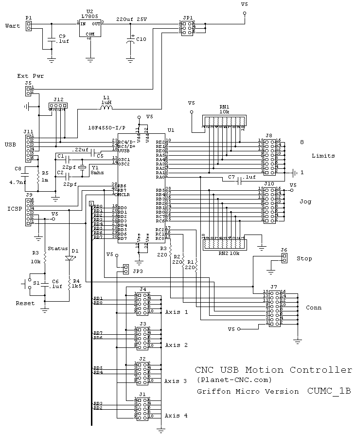
This version of the Planet-CNC, CNC USB Motion Controller is very similar to the original with the following differences: added a 5V regulator, added a connector for a USB panel mount, changed the ICSP to the PicKit2 pinout and changed sip resistors to 10 pin (readily available). The 10 pin driver connector is PMinMO compatible and is correctly oriented. The USB connector has been moved to the front for insertion thru the front panel of the electronic enclosure.
In addition to the CUMC, a jog switch panel pcb and a limit switch junction pcb are in the works. At some point a enclosure layout will be added to this post.
Bill of Materials for CNCCUMC_1B
http://www.batchpcb.com/index.php/Products/57241
Bill of Material for C:\PCB PIC\CNC_CUMC_01B.PCB | ||||
On 4/9/11 at 5:59:46 PM | ||||
Count | Label-Value | Pattern | Designation(s) | Mouser # |
2 | 22pf | cap100s | C1 C2 | 80-C315C220J1G |
1 | 220uf | C+300D140 | C10 | 647-UHE1E221MPD |
3 | .1uf | cap100s | C3 C5 C6 | 80-C320C104M5R |
3 | .1uf | cap100 | C7 C9 | 80-C320C104M5R |
1 | .22uf 50V 20% | cap100 | C4 | 80-C320C224K5R |
1 | .0047uf | cap100 | C8 | 80-C315C472K5R |
1 | 1N5817 | DIODE0.35 | D1 | 511-1N5817 |
1 | ferrite bead | AXIAL0.3 | FB | 623-2743001112LF |
4 | IDC10-S | XIDC10 | J1 J2 J3 J4 | 517-D2510-6002-AR |
3 | IDC16-S | XIDC16 | J10 J7 J8 | 517-D2516-6002-AR |
1 | USB-S B | USB-BS | J11 | 523-UE27-BC54-130 |
1 | IDC Header 4 | 620454-4 | J12 | 571-6404564 |
2 | IDC Header 2 | 620454-2 | J5 J6 | 571-6404562 |
1 | IDC Header 6 | 620454-6 | J9 | 571-6404566 |
1 | DHeader 6 | IDC6 | JP1 | 517-836-01-04 |
2 | SHeader 2 | SIP2 | JP2 JP3 | 517-647-01-02 |
1 | LED green | LED | LD1 | 638-HLMP-1790 |
1 | Power Jack | PJ-102A2 | PB1 | CUI PJ-102A Digikey |
3 | 220R 1/8W | AXIAL0.25 | R1 R2 R3 | 299-220-RC |
1 | 10k 1/8W | AXIAL0.25 | R4 | 299-10K-RC |
1 | 1meg 1/8W | AXIAL0.25 | R5 | 299-1M-RC |
1 | 1K5 1/8W | AXIAL0.25 | R6 | 299-1.5K-RC |
2 | 10K SIP 9P | SIP9 | RN1 RN2 | 652-4610X-1LF-10K |
1 | TS 3.5x6mm | SW635 | S1 | 101-TS4311T2601-EV |
1 | 18F4550 | DIP40.6X2025 | U1 | 18F4550-I/P |
1 | L7805 | TO252AB | U2 | 511-L7805CD2T-TR |
1 | 8mhz | XTAL4 | Y1 | 520-HCU800-20X |
1 | 40 pin IC socket | U1S | 517-4840-6004-CP | |
Getting the CUMC Board Working
1) Install the USB driver and the CUMC software on your PC (See manual)
2) Using PIC programmer install Bootloader in 18F4550. I used MeLab serial programmer. PicKit2 or PicKit3 can also be used or one of your choice.
3) Connect Jumper from Jog8 to Vcc. Press reset. Led should start blinking.
4) Remove jumper and insert USB connector.
5) Start PC software.
6) Using software do: Machine-Firmware-Update
7) Firmware should update and give a response.
Assembled Board
Below is a picture of the assembled board.


Unhappily, Batchpcb failed to place the top silk screen. Why, I don't know, since it was in the zip file. The back of the pcb has a ground plane and the orange markers in the above layout are the ground points. This print does show the top screen for reference.
I plan to make some changes to the board once I have this prototype working. As I assembled this prototype, some changes have already been made to the layout to accommodate , for example, a jog switch pcb, etc.
The next step is to program the 18F4550 and test the pcb.
Important Note:
Our version does not have the same 16 pin connector orientation as planet_cnc. This can be fixed during assembly by rotating the the JOG and the Limit connectors by 180 degrees. To make sure, go to planet_cnc store and double click their pcb image. Make sure the connectors have the same orientation. By doing this the connector pinout will match the manual. It should be pointed out that the planet_cnc overlay pdf is wrong and does not match the manual.
Our version 2 will fix the connector orientation problem, but will not be sent to Batchpcb until the present version is completely tested.
Update:
Since a complete electronic package is our goal, a JOG switch pcb and a limit switch pcb have been designed. The JOG pcb will mount on the electronic case front panel and the limit switch pcb will mount at the CNC router.Cabling the limit switch pcb will be as follows: IDC-16 pin on CUMC to DB-15 pin on rear panel to DB-15 pin at router to 16pin IDC. A small aluminum box on rear of CNC router will house electrical interconnects, including connectors to motors.
As the prototype of the electronic motion control RepRap3. I will release the job design, and publish the experiences of others.
ReplyDeleteUSB Motion Controller
Hi, you have the firmware of CUMC Board? You can send me, please!
ReplyDeletethax man....
ReplyDelete